In any wireless technology unlike 4G, 3G and 2G first we must know about the UE power-on procedure. In this article, we will discuss in detail the UE power procedure in 5G.
UE Switch on procedure in 5G:
The LTE power-on procedure is much similar to the UE switch-on procedure in 5G if you are aware of the LTE power-on procedure then you will easily understand the UE power-on procedure in 5G.
UE power on procedure in 5G here are the Steps:
1. Frequency Search (Scan the entire frequency bands)
2. Cell Search – will decode SSB (PSS+SSS and PBCH/MIB) UE would find multiple cells and beams in this process of SSB (Synchronization Signal Blocks) Decoding.
3. PDSCH-SIB decoding (RMSI and OSI Decode).
4. Cell Selection.
5. 4-Step RACH procedure or 2-Step RACH procedure.
6. Registration/Authentication/Attach.
7. PDU session establishment
8. IP Packet receive and transmit.
Frequency Search or Acquisition (Scan the entire frequency bands):
After UE power on the first process, UE will do i.e. frequency scan. UE power on does not mean that UE switches off and on it can be Airplane on and off, switch off and on, out of the coverage-to-coverage area, switch to Airplane mode and fly into another country and then switch back to the normal mode, turn it off right away in the middle of registration and then turned it on.
There are two types of frequency scan or acquisition:
- SLS (Store List search): After powering on, the UE will start scanning the frequencies that were already stored in its memory. This frequency is stored by UE in its previous attachment.
- DBS (Deviated Band Search): In this case, UE does not have any idea about which frequency it has to try to camp on. It will start doing the blind search means scanning all the frequencies of the whole band.
For example,
let’s take one example UE supports 5G Band FDD Band N1 and N2 and TDD Band N77 and N78.
UE may use any frequency channel from FDD Band N1, nr-ARFCN range (158200, 164200) then the channel raster will start to detect the operating frequency with the strongest RSSI.
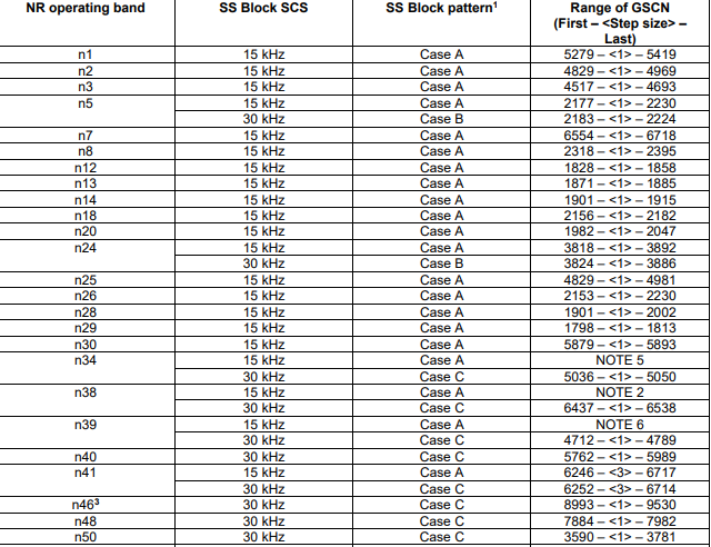
We have a table for frequency range that has GGSN specified 3GPP specs 38.101 table no 5.4.3.3-1 go through that table once. In the initial acquisition case, GSCN raster will apply because we don’t have any info that’s why GSCN so that UE will tune.
Now UE will know the frequency now it will start looking for time and frequency domain resources. So, the next step is Initial Acquisition/SSB Decoding.

Initial Acquisition/SSB Decoding in UE Power on Procedure:
In LTE we have PSS, SSS and MIB separately but in NR we have SSB (Synchronization Signal Block).
PSS (Primary Synchronization Signal): PSS has 3 values i.e., 0,1 & 2.
SSS (Secondary Synchronization Signal): SSS has 336 values i.e., 0 to 335.
In 5G-NR, the PSS is the same as LTE but the SSS is increased.
PCI in 5G: With the help of PSS and SSS we can decode the PCI of 5G. PCI value is double in comparison to LTE i.e. 1024.
NIDCell = 3 * NID(1) + NID(2)
PCI = (3 * 335) + 2 = 1007
What is SSB (Synchronization Signal Block) in 5G?
SSB is the combination of PSS (Primary Synchronization Signal), SSS (Secondary Synchronization Signal, PBCH/MIB(Master Information Block) and PBCH-DMRS(Demodulation Reference Signal). In NR, we have a minimum requirement of 20RBs.

-SSB takes the 20RBs in the frequency domain and each SSB occupies 4 consecutive OFDM signals in the time domain and PSS, SSS and PBCH are always together in consecutive OFDM signals.
-0th OFDM symbol occupies by PSS and 2nd OFDM symbol occupies by SSS and PBCH occupies the 1st, 3rd complete OFDM Symbol and the 0th and 2nd partially OFDM symbols.

- PBCH total we have 576 REs out of which PBCH DMRS we have 1/4th REs.
- PBCH = 576REs
- PBCH DMRS= 576/4 = 144 Res
How to find the PBCH DMRS on which OFDM symbol occupies?
For that, we need to know about the PCI for NR then we can calculate that.
For example, PCI is 955
- V= 0, V+4
- V= Ncell id mod4
- V= 955 mod 4
- V=3
So, the location will be: 3, 7,11,15,19,23…. so on.
SSB Periodicity:
As per 3GPP specs periodicity of SSB {5ms, 10ms, 20ms, 40ms, 80ms or 160ms.} commonly we use 5ms and 20ms SSB periodicity and Initial Acquisition in SA attach UE assumes SSB periodicity 20 ms because in that case, we don’t have SSB periodicity information.
Longer SSB periodicities enhance network energy performance, shorter periodicities facilitate faster cell search for UEs.
SSB Candidate:
SSB Candidate withinSS burst set depends upon the SCS(0,1,2,3,4) and NR frequency band. Based on 3GPP TS 38.213 (4.1) specification.

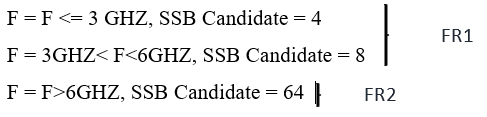
30KHZ we have two cases for that we can differentiate in Time Domain other things are the same.
We have 64 SSB candidates.
-In the radio frame we can only use the half frame for SSB.

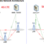
Also Read:- 5G Architecture and what is the difference in 4G and 5G architecture?
Image source: howltestuffworks.blogspot.com
SSBs Information Element:
We can configure the SSB IE’s under SIB1 and RRC connection reconfiguration.
For Initial access, we must define SSB under SIB1 and for NSA we can define SSBs under RRC connection reconfiguration.
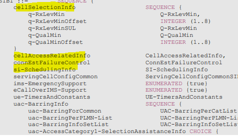
SSB Configuration for Initial Access when UE IDLE mode/SIB1:
SSB comes under ServingCellConfigCommon on SIB1.

SSB Configuration for NSA RRC Reconfiguration:
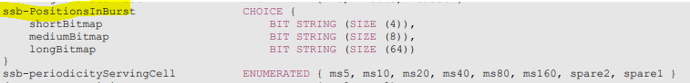
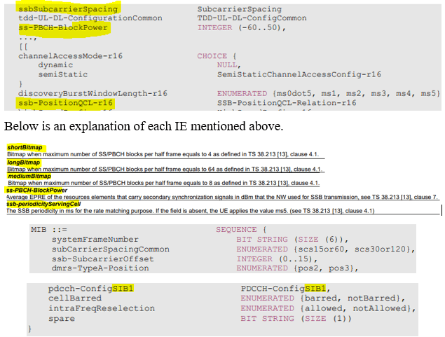
Ssb-PositionsInBurst The first/leftmost bit corresponds to SS/PBCH block index 0, the second bit corresponds to SS/PBCH block index 1, and so on. Value 0 in the bitmap indicates that the corresponding SS/PBCH block is not transmitted, while value 1 indicates that the corresponding SS/PBCH block is transmitted. The network configures the same pattern in this field as in the corresponding field in ServingCellConfigCommonSIB. Operations with shared spectrum channel access in FR1, only mediumBitmap is used, and for FR2-2, longBitmap is used.
Below is an explanation of each IE mentioned above.
UE power on Procedure MIB Decoding:
After SSB decodes successfully then UE will start decoding the MIB and SIB1. MIB will decode via PBCH.
MIB is always transmitted on the BCH with a periodicity of 80ms and repetitions made within 80 ms (TS 38.212 [17], clause 7.1) and it includes parameters that are needed to acquire SIB1 from the cell.
The first transmission of the MIB is scheduled in subframes as defined in TS 38.213 [13], clause 4.1 and repetitions are scheduled according to the period of SSB;
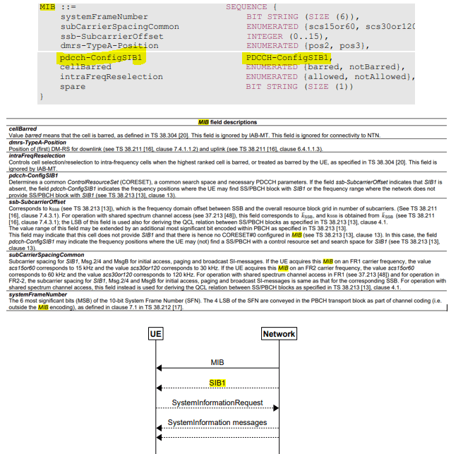
we will get the information on CORESRT0 or PDSCH CONFIG SIB1 which is a very important parameter to decode SIB1, SFN, Subcarrierspacingcommon, cell barred and itrafrequencyreselection. -NR MIB has total 56-Bits in total, 24 Bit MIB payload and 8-Bits PBCH Payload and 24-Bit CRC appended.
PDSCH-SIB decoding (RMSI and OSI Decode):
UE successfully decoded MIB, so now it decodes the SIB1 decoding will start in MIB we got the PDSCH-ConfigSIB1 or CORESET0 information in this we get the information required for monitoring of PDCCH for scheduling PDSCH that carries SIB1.

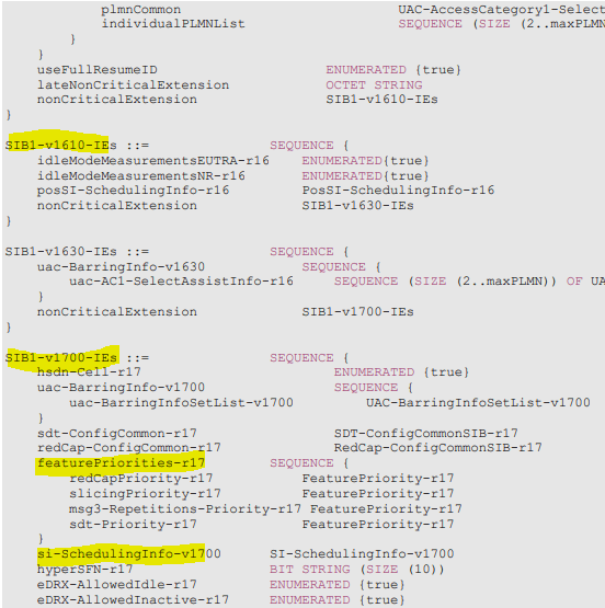
-SIB has REDCAP-related parameters and featurepremables parameters.
Also read:- What is NCD-SSB and CD-SSB in REDCAP NR R17?
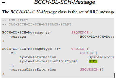
-In NR SIB1 also known as RMSI (Required Minimum System Information) and divided into two parts minimum SI and Other SI (On-demand System Information).
GnodeB transmits Other SI only when UE(s) is explicitly requested to GnodeB.

-In NR SIB1 priority is 160ms and repetition periodicity is within 160 ms.
-SIB1 carries the most Cell selection info, SSB scheduling information, RACH configuration which earlier in LTE comes under SIB2.
5G NR Cell Selection Procedure:
What is cell selection?
When you power on the mobile device, in most cases the device is under a circumstance where it sees many base stations (gNB) around it.
In some cases, UE would be surrounded not by the multiple base station from one network operator but by the multiple base station from different network operators.
Out of those many cells, UE can camp on (register) only one cell. Then the question is which specific single cell the UE has to register.
For this UE goes through a specific decision-making process to pick up a specific Cell to register, this specific decision-making process is called ‘Cell Selection’.
Two types of cells:
Acceptable Cell
An acceptable cell is a cell that may not meet all the requirements of a suitable cell, but it satisfies the minimum conditions to make an emergency call. The minimum conditions include:
- The cell must not be barred.
- The cell selection criteria should be met.
2. Suitable Cell
A suitable cell is a cell that a UE (user equipment) may camp on for normal service.
Cell is part of either the selected PLMN (PLMN that has been selected by the NAS, either manually or automatically), or the registered PLMN (PLMN on which certain Location Registration outcomes have occurred), or a PLMN of the Equivalent PLMN list, according to the latest information provided by NAS.
- Cell is not barred.
- Cell should not be forbidden “forbidden tracking areas for roaming”.
- Cell selection criteria are fulfilled.
Types of Cell selection:
Cell selection is performed by one of the following two procedures:
Initial cell selection:
The UE shall scan all NR bands to find a suitable cell.
On each frequency, the UE only needs to search for the strongest cell.

A suitable cell is found, and it will be selected.
The UE shall scan all NR bands to find a suitable cell.
2. On each frequency, the UE need only search for the most robust cell.
3. Suitable cell is found, then it will be selected.
Cell selection By Stored information:
This procedure requires stored information on frequencies and optionally also information on cell parameters from previously received measurement control information elements or from previously detected cells.
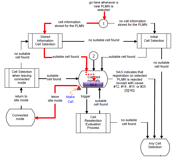
Once the UE has found a suitable cell, it shall select it.
There is no suitable cell is found, the initial cell selection procedure in a) shall be started.
Cell Selection Criterion:
Cell selection criterion S is fulfilling?
Srxlev > 0 AND Squal > 0
where:
Srxlev = Qrxlevmeas – (Qrxlevmin + Qrxlevminoffset )– PCompensations – Qoffsettemp
Squal = Qqualmeas – (Qqualmin + Qqualminoffset) – Qoffsettemp
LTE and NR Cell Selection Difference in Cell Selection Criteria:
RACH Procedure: Next step for UE
Now UE will start doing Contention-based RACH as SIB1 got the IE’s which is required to do a RACH procedure.

Detailed RACH procedure explained in this Blog: https://trickyard.com/rach-procedure-5g-nr/